Guides6 min readFloorGen team
Floor Plan to DXF: Export a Plan for AutoCAD, LibreCAD, QCAD
How to export a floor plan to DXF or SVG: what layers and units the file has, how to open it to scale in AutoCAD, LibreCAD or QCAD, and what to send a drafter.
To get a floor plan to DXF, draw it in a tool that stores real wall geometry and export from there; a picture of a plan cannot be turned into clean CAD lines. In FloorGen, open Export, choose the CAD and 3D tab, pick DXF and download. You get an AutoCAD R12 DXF with a layer per kind of object, drawn at full size in centimeters, which AutoCAD, LibreCAD, QCAD and most other CAD programs open.
The details below are what decide whether the file is useful when it lands on someone else's screen: units, layers, what is and is not in the file, and how to bring it in at the right size.
Exporting a floor plan to DXF in FloorGen
- Open the project and the floor you want. FloorGen is free and the export works without an account.
- Open Export and choose the CAD and 3D tab. Its format switch offers SVG, DXF and glTF.
- Choose DXF. On a project with more than one floor, choose between the open floor and all floors side by side, each under its name.
- Download. The file is named after the project and floor, ending in
-plan.dxf, or-all-floors.dxffor every floor.
The preview in the dialog is a picture of the open floor for reference. The DXF itself is drawn in layers, not as that picture.
What is in the DXF
The file is plain ASCII DXF in the AutoCAD R12 format (AC1009 in its header), chosen because nearly every CAD program, old or new, reads it. Every object goes on one of eight layers, each with its own color:
| Layer | Contents | Entity types |
|---|---|---|
| WALLS | Wall outlines with door and window openings cut out | Closed polylines |
| ROOMS | Room boundaries, room names and net areas | Closed polylines, text |
| DOORS | Door leaves and swing arcs, and passage openings | Lines and polylines |
| WINDOWS | Window symbols | Lines and polylines |
| FURNITURE | Furniture and fixtures as footprint outlines, with labels | Closed polylines, text |
| STAIRS | Stair outlines and walk lines (including stairs passing through from the floor below), and lift shafts | Polylines, text |
| DIMENSIONS | Wall dimension strings and pinned measurements | Lines and text |
| NOTES | Text notes and the north arrow | Text, lines, polylines |
Three things about the file are worth knowing before you send it on:
- Geometry is in centimeters, at full size. A 40 ft wall is about 1,219 units long. FloorGen stores plans in centimeters internally and writes them out unscaled, with the header's units set to centimeters.
- Labels follow your project's units. In a feet-and-inches project, the dimension text and room areas read in feet, inches and ft², even though the geometry underneath is in centimeters.
- Dimensions are drawn, not associative. Each dimension is lines plus a text label, not a CAD DIMENSION entity. If a drafter stretches a wall, the number will not update; they will usually redimension in their own style anyway.
Not in the file: wall hatching or fills, 3D information (for that, see floor plan to 3D), and the traced background image if you drew over one. Walls come as outlines, so a drafter who wants a solid poché adds a hatch to the WALLS layer.
Opening it at the right size
The units flag in the header ($INSUNITS) is set to 5, which means centimeters. Newer AutoCAD versions read it; some R12 readers and older programs ignore it and treat the drawing as unitless. Either way the numbers are centimeters, so the fix is always the same:
| You want | Scale the drawing by | Check |
|---|---|---|
| Inches | 1 ÷ 2.54 = 0.3937 | A 40 ft wall should list as 480 in |
| Feet | 1 ÷ 30.48 = 0.03281 | A 40 ft wall should list as 40 |
| Millimeters | 10 | A 40 ft wall should list as 12,192 mm |
| Meters | 0.01 | A 40 ft wall should list as 12.19 m |
- AutoCAD: insert the DXF as a block (or open it and copy it into a drawing), then use SCALE with a base point at a corner and the factor above. Measure one known wall with DIST to confirm.
- LibreCAD: open the file, set the drawing units under the drawing preferences, select everything and use the scale modify tool with the factor above.
- QCAD: open the file, confirm or set the drawing unit in the drawing preferences, then scale the selection by the factor above.
Menu names move around between versions, so treat these as the steps rather than exact clicks. The one check that always works: measure a wall whose length you know.
An example: the 800 sq ft ADU
FloorGen's 800 sq ft 2-bed ADU template is drawn 40 × 20 ft to the outside of its walls (800 ft² outside), with 700.5 ft² of net room area inside. Exported to DXF, its WALLS layer holds the outer shell and the interior partitions with openings cut out for the doors, the windows and the wide cased openings that join the kitchen to the dining room and the dining room to the living room. The ROOMS layer carries each room's outline with its name and area, so a drafter can turn rooms off and still see walls, or vice versa.
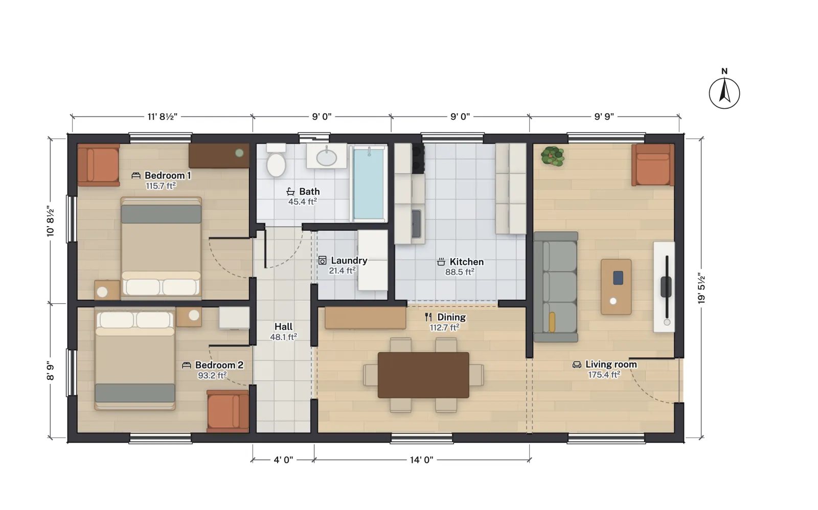
| Room | Net area |
|---|---|
| Living room | 175.4 ft² |
| Bedroom 1 | 115.7 ft² |
| Dining | 112.7 ft² |
| Bedroom 2 | 93.2 ft² |
| Kitchen | 88.5 ft² |
| Hall | 48.1 ft² |
| Bath | 45.4 ft² |
| Laundry | 21.4 ft² |
| Total | 700.5 ft² |
These areas print as text on the ROOMS layer. A drafter checking the conversion can compare a room's polyline area in CAD (converted from cm² to ft² by dividing by 929.03) with the label.
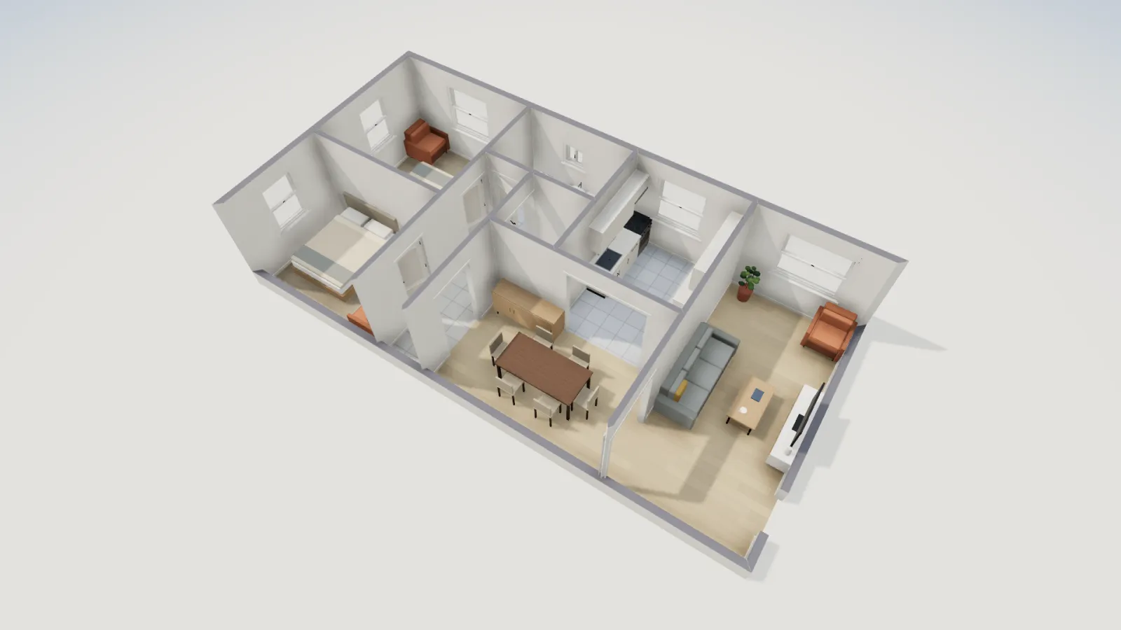
SVG: the same drawing for design tools
The SVG option on the same tab writes the same layers as named groups (Inkscape-style layers, so Figma and Illustrator list them as well). It is drawn at real size, 1 SVG unit to 1 cm, and the file declares its width and height in centimeters. Use SVG for a presentation board, a real-estate flyer you style yourself, or a laser-cut model; use DXF for anyone who drafts.
Handing the file to a drafter
A DXF saves a drafter the most tedious part, redrawing your layout from a sketch, but they will still rework it into permit drawings with their own title block, wall types and notes. Send them a small package so nothing gets lost:
- The DXF, with a line in your email saying it is in centimeters at full size.
- A scaled PDF from the Print set tab, which prints each floor on Letter, Tabloid, ARCH C or ARCH D (or ISO sizes) at an architectural scale such as 1/4" = 1'-0", with a title block. It shows them what the plan should look like.
- The project file from the Project file tab, if they or you want to reopen it in FloorGen later.
- What you have verified on site. A plan you drew is a design intent until someone measures; say which dimensions are measured and which are planned.
What a permit set needs beyond the plan (site plan, elevations, sections, structural details) depends on your jurisdiction. Drawing floor plans for a building permit goes through the usual list, and exterior elevation drawings shows how FloorGen draws those, also exportable to DXF.
More from the blog
Guides6 min read
Free Floor Plan Software and Apps Compared (2026)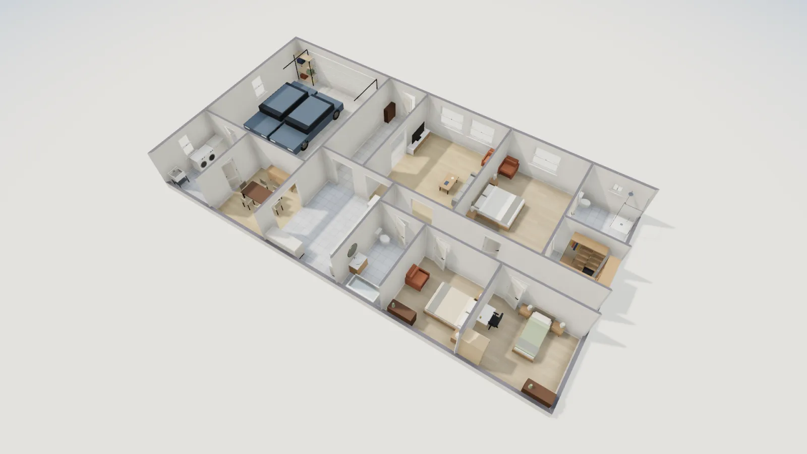
Guides8 min read
How to Convert a Floor Plan Image to an Editable Plan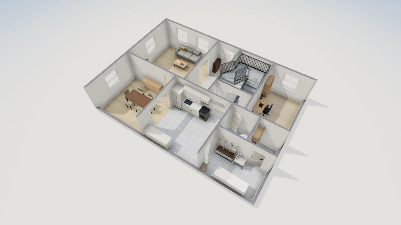
Guides5 min read
Convert a 2D Floor Plan to 3D and Walk Through It