GuidesUpdated 8 min readFloorGen team
How to Convert a Floor Plan Image to an Editable Plan
How to convert a floor plan image or PDF page into an editable plan: set the scale from one known length, detect or trace the walls, then check the sizes.
To convert a floor plan image to an editable plan, put the image under a drawing, tell the software how long one line on it really is, and redraw the walls over it, either by hand or by letting the software propose them from the thick dark lines. The picture itself never becomes editable. What you get is a new plan with real walls, drawn to the scale you set, which you can then change, measure and export.
This guide walks through that process in FloorGen, which runs in the browser, is free, and works without an account. It covers what kind of image works, how to set the scale accurately, what automatic wall detection can and cannot do, and how to check the result before you trust a single dimension.
Which images you can convert to an editable plan
Most people have one of four things: a photo of the sales brochure, a scan of the builder's drawings, a PDF from the county or the original architect, or a screenshot of a listing. FloorGen's trace tool accepts PNG, JPG, WebP and GIF images and PDF files. It checks the file by its bytes, not its name, so a misnamed file is still read correctly.
| Input | Limit | Notes |
|---|---|---|
| Image (PNG, JPG, WebP, GIF) | 15 MB, up to 20,000 px per side | A photo straight off a phone is well inside this |
| 50 MB | You pick one page; it is drawn under the plan as an image | |
| Multi-page PDF | Thumbnails of up to 60 pages | Any later page can be reached by typing its number |
The better the source, the less redrawing you do. A clean scan or a vector PDF from an architect is ideal. A photo taken at an angle works, but straighten it first (below), and expect lines near the edges of the frame to be slightly curved by the lens. A listing screenshot is usually the weakest source: often it is a marketing drawing that was never to scale.
Step 1: put the image under the plan
Open a blank project, or start from a template and clear it. Press I, use the trace button in the toolbar, or choose Trace an image on the empty canvas ("Use a floor plan photo, scan or PDF"). Pick your file.
- For an image, it lands under the plan at 50% opacity, sized at a first guess of about 33 ft (10 m) wide. That guess is only there so you can see it; the next step fixes it.
- For a PDF, a Choose a page to trace dialog shows page thumbnails. Click the floor plan page and press Use page. If you later add a second floor to the project, the trace tool offers the same PDF again so you can pick the upper-floor page without hunting for the file.
The image is stored in your browser with the project, not uploaded. If you export the project file, the traced image goes with it.
Step 2: set the scale from one known length
This step decides whether every later number is right. FloorGen switches to the Set image scale tool (shortcut K) as soon as the image is placed. Click two points on the image a known distance apart. A dialog says how long the marked line currently measures and asks how long it is in reality; type it in feet and inches, such as 14' 9", and press Apply scale.
Which length you pick matters more than how carefully you click:
- Use the longest printed dimension you can find, ideally an overall exterior dimension such as 52'-0". A click that is off by a few pixels is a much smaller error on a 52 ft line than on a 3 ft door.
- Click the same reference points the dimension uses. Architectural plans usually dimension to the outside face of framing or to wall centerlines. Click the tick marks of the dimension string, not the wall edges, unless you know they coincide.
- Avoid door widths as a reference. A door symbol drawn at "3'-0"" is often drawn approximately, and the opening may be the door leaf or the rough opening.
- No dimensions printed? Measure one long wall in the real house and use that.
If the scan is crooked, fix that first. Select the image and use Straighten in its properties, then mark a wall edge or a printed line that should be level or plumb and choose Make horizontal or Make vertical. There is also Rotate 90° for a page scanned sideways. Then Lock the image so it cannot be dragged by accident while you draw.
Step 3: detect the walls, or trace them
With the scale set, the image's properties offer Detect walls. It looks for thick, dark, straight lines and proposes them as walls, drawn dashed over the image. A bar at the bottom says how many it found, for example "18 walls found". Click any dashed wall you do not want to remove it, then press Add all to turn the rest into real walls, or Discard to throw them away. Adding them is a single step you can undo.
Detection runs in your browser and nothing is sent anywhere. It works from real-world sizes, which is why it needs the scale first:
| Rule | Value | What it means for your image |
|---|---|---|
| Thickness | About 3 to 16 in (7 to 40 cm) | Thin lines such as dimension strings, furniture and hatching are skipped |
| Length | At least about 2 ft (60 cm) | Short stubs beside doors may be missed |
| Resolution | A wall must be at least 2 px thick in the image | A tiny thumbnail is refused as too coarse; use a larger scan |
| Direction | Walls along the image axes, plus angled walls | Straighten a tilted scan first for the best result |
Detection gets you the bulk of the walls on a clean drawing. It will not read door swings, window symbols, text or curved walls, and on a busy brochure plan with shaded rooms it can find nothing; the message then says walls are read from thick dark lines and suggests setting the scale and straightening the scan. In that case, trace by hand: press W for the wall tool and click corner to corner over the image. You can type a length while drawing (Tab moves to the angle) and hold a key to lock the wall horizontal or vertical.
Once the walls close into loops, FloorGen finds the rooms by itself and labels each with its net area. Name the rooms, then add doors (D) and windows (N) on the walls where the image shows them.
Step 4: check the sizes before you trust them
A traced plan is only as good as its weakest assumption, so check it against the source in three ways.
- Overall dimensions. Use the tape measure (M) to measure the outside of the building and compare with the printed overall dimension. If it is off by more than an inch or two on a long wall, redo the scale with a longer reference.
- A second printed dimension, in the other direction. A scan or a photo can be stretched more one way than the other. If widths agree and depths do not, the source is distorted; tracing over it will carry that error into every room in that direction.
- Room areas. Compare FloorGen's room areas with any on the source, but remember what each one measures (next section).
Why your areas will be a little smaller than the brochure
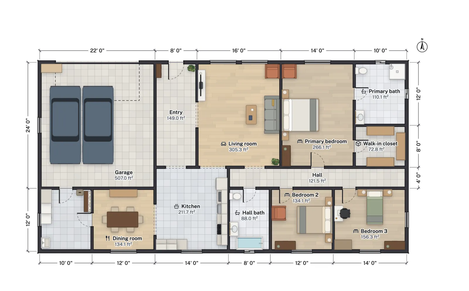
FloorGen labels each room with its net area, measured to the inside faces of the walls. A drawing that says a garage is 22 × 24 ft is usually quoting the size on the wall grid or to the outside. In FloorGen's 3-bed ranch template, the garage drawn 22 × 24 ft on its wall grid (528 ft² on that grid) measures 507 ft² net inside its walls. The whole ranch is 2,366 ft² of net room area but about 2,578 ft² to the outside of its walls. A traced room that comes out a few percent under the label is normal; one that is 15% off is a scale problem. See how to calculate square footage for which figure a listing or an appraiser uses.
What you can do once it is a real plan
This is the point of converting the image. With real walls, the plan behaves like any other FloorGen project:
- Move a wall and the rooms on both sides resize, with their doors riding along.
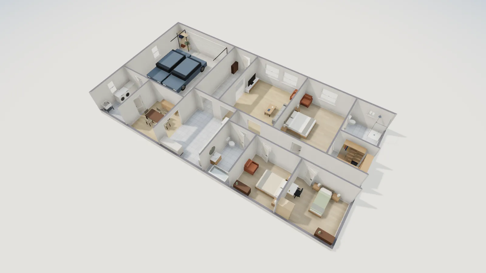
- Switch to 3D (press 3, or the 2D/3D control) and walk through it.
- Run the IRC checks on room sizes and stairs from the Issues list.
- Export a scaled print set PDF, a DXF for a drafter, or a 3D model, from Export.
- Hide the traced image or turn its opacity down once you are done with it.
If you are documenting a house you already own, drawing a floor plan of an existing house covers what to measure on site to fill the gaps a scan leaves, and how to draw a floor plan covers drawing one from scratch.
Tracing with an AI agent
If you connect an AI app to FloorGen over MCP, it can do the first two steps too: the server has set_background to place an image (PNG, JPEG, WebP or GIF, up to 4 MB) and calibrate_background to scale it from a known length, in its trace toolset. You still check the result the same way. The setup is in connecting Claude, ChatGPT and Cursor.
The floor plan from image page sums up the tracing tool and links straight to an empty plan with tracing ready.
More from the blog
Guides6 min read
How to Find Blueprints or a Floor Plan of My HouseGuides6 min read
Can I Draw My Own Plans for a Building Permit? How-To
Guides8 min read
How to Draw a Floor Plan: A Step-by-Step Guide (2026)