Guides6 min readFloorGen team
Exterior Elevation Drawing: What It Shows and How to Make One
What an exterior elevation drawing shows, why permit reviewers ask for one, and how to generate north, south, east and west elevations from a floor plan.
An elevation drawing is a flat, straight-on view of one side of a building, drawn to scale with no perspective: the walls, doors, windows and roof as you would see them standing far back from that face, with the key heights marked. A typical house set has four exterior elevations, one per side, and most building departments ask for them with a permit for a new house, an addition or an ADU because they show what a floor plan cannot: how tall the building is and what it looks like from the street and the neighbors.
This guide covers what belongs on an elevation, why reviewers care about it, and how FloorGen draws elevations directly from a floor plan, using its 3-bed ranch template as the example.
What an elevation drawing shows
A plan shows the building from above; an elevation shows one face of it from the side. Everything is drawn at true size in the plane of that face, so you can measure heights and widths with a scale rule. A useful exterior elevation has:
| Element | What it tells the reader |
|---|---|
| Grade line | Where the ground meets the building; the base for height measurements |
| Floor levels | Finished floor heights above grade, one datum per storey |
| Eaves and ridge heights | Where the roof starts and its highest point; the figure zoning height limits are usually checked against |
| Roof shape and pitch | Gable, hip or flat, and how steep, usually as rise per 12 in of run |
| Doors and windows | Size, position, head and sill heights, often tagged to match the door and window schedule |
| Exterior materials | Siding, brick, stucco, roof finish, called out with notes |
| Overall dimensions | Total height and the width of the face |
Elevations are named either by compass direction (north elevation, east elevation) or by position (front, rear, left, right). A "north elevation" is the face that points north, so you look at it while facing south. Angled faces, such as a bay or a wing set at 45°, get their own elevation looking square at that face.
Why permit reviewers ask for elevations
The model codes do not list "four elevations" as such. The 2021 IRC R106.1.1 says construction documents must be clear enough to show the location, nature and extent of the work and that it conforms to the code, as the building official determines. Building departments then publish their own submittal checklists, and most residential checklists include exterior elevations. The reasons are practical:
- Height limits. Zoning codes cap building height, often measured from grade to the ridge or to the midpoint of the roof, depending on the local definition. The elevation is where the reviewer checks it.
- Window and door positions. Sills high enough for safety, egress windows low enough to climb out of (see legal bedroom requirements), and openings near property lines all show up on the elevation.
- Design review. Historic districts, HOAs and some ADU programs review materials, roof form and how the building faces the street.
- Fire separation. Walls close to a lot line may limit openings; the elevation shows how many there are.
How FloorGen generates elevations from the plan
In FloorGen you do not draw elevations; they are built from the 3D model of the plan, so they always match it. Open the plan summary panel (the overview of the floor) and find Elevations. It shows four thumbnails, North, East, South and West elevation, which follow the project's north arrow. Add view saves an extra elevation for an angled façade or a bay, aimed by the bearing the façade faces in degrees from north; a project can hold up to 12 saved views.
Click a thumbnail to open the elevation. The dialog has:
- Drawing style: Lines, Tones or Colour.
- Levels and heights: level datums on the right (Site, each floor level, Eaves, and Ridge, or Top of parapet on a flat roof) and the overall height on the left, in your project's units.
- Door and window tags: a tag over each opening matching the door and window schedule (D1, W1 and so on).
- Material notes: callouts such as Brick, Plaster, Painted wall, Gable and the roof finish.
- Roof: show or hide the roof.
- Façade notes: a list of things worth a second look, such as a window whose head does not line up with the others on that floor, a sill out of line, an opening too close to a corner, or an upper window sitting off the one below.
Click a door or window in the elevation, or pick it from the list, to change its Sill and Height right there; the plan and 3D view update with it. Show on plan jumps to that opening on the floor plan.
Setting the roof
A new project starts with a flat roof behind a parapet. For a pitched roof, open the 3D view and set Roof shape to Gable or Hip, then the Pitch and Overhang; the elevations draw the same roof. FloorGen's pitch is in degrees, so convert from the usual US rise-over-run: 4/12 is about 18.4°, 6/12 about 26.6° and 8/12 about 33.7°. If the top floor is not a rectangle, a pitched roof covers its bounding box, which is fine for a sketch but not for a roof with valleys; draw that roof properly in your permit set.
An example: the 3-bed ranch
FloorGen's 3-bed ranch with 2-car garage template is a single storey, about 70 ft 6 in by 36 ft 6 in to the outside of its walls, with the garage at one end. Its street side, the top edge of the plan, has the 16 ft garage door at one end, then the 36 in front door, two living room windows, the primary bedroom window and a small bath window. The footprint is a plain rectangle, so a gable or hip roof fits it exactly. Turn on door and window tags and each window carries the same tag as the schedule, which makes it quick to see whether windows of the same size really share a head height.
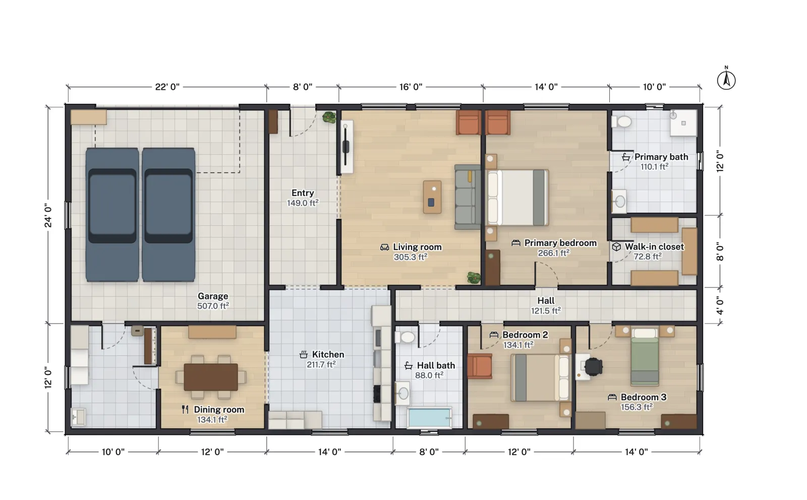
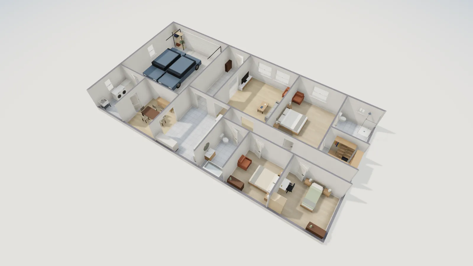
Elevations are where a plan that looks fine from above shows its awkward spots: window heads at three different heights on one wall, a window squeezed against a corner, a garage door that dominates the front. The façade notes catch the first two automatically.
Exporting elevations
Each elevation dialog has three downloads:
| Format | What you get | Use it for |
|---|---|---|
| A landscape A4 sheet at the largest standard ratio scale that fits (stated on the sheet as 1:n), with levels, tags and notes as shown | Printing, review, attaching to an application | |
| SVG | A vector drawing in the chosen style | Presentation boards, editing in Illustrator, Inkscape or Figma |
| DXF | Lines and text in layers, like the plan export | Handing to a drafter (see floor plan to DXF) |
The Print set in Export also adds every elevation that draws something, after the building summary and sections, when its building summary option is on. Note that elevation sheets use ratio scales such as 1:50 or 1:100 rather than the architectural scales (1/4" = 1'-0") the floor-plan sheets of a feet-and-inches project use, so state the scale clearly if you print them for a reviewer.
What FloorGen's elevations leave out
- Sloping ground. Grade is drawn as a level line at the site datum. On a sloping lot, reviewers usually want existing and finished grade drawn on each face.
- Complex roofs. The automatic roof is flat, gable or hip over the top floor. Dormers, valleys and shed roofs need drawing elsewhere.
- Trim and detail. Fascia, trim boards, gutters and siding patterns are not drawn; material notes name the finish instead.
- Structural and code notes. Elevations here are a design drawing, not a stamped construction document.
For the rest of a permit set, see drawing floor plans for a building permit. A site plan of the lot usually goes with them.
More from the blog
Guides6 min read
Can I Draw My Own Plans for a Building Permit? How-To
Guides5 min read
Convert a 2D Floor Plan to 3D and Walk Through It
Guides6 min read
Floor Plan to DXF: Export a Plan for AutoCAD, LibreCAD, QCAD