Guides7 min readVinit Kumar
What Is a Reflected Ceiling Plan? How to Draw One
A reflected ceiling plan shows the ceiling as if mirrored on the floor: lights, heights, soffits and vents. What it includes, its symbols and how to draw one.
A reflected ceiling plan (RCP) is a drawing of the ceiling as if it were reflected in a mirror lying on the floor. Because it is a reflection rather than a view looking up, it has the same orientation as the floor plan below it: a light drawn in the north-east corner of the RCP is in the north-east corner of the room. It shows what is on or in the ceiling, such as light fixtures, fans, vents, soffits, beams and ceiling heights, so the electrician, the HVAC installer and the drywall crew can work from one sheet.
Below: why it is drawn reflected, what goes on one, the usual symbols, how to draw an RCP step by step, and an honest look at how far FloorGen gets you. For the lights themselves see recessed lighting spacing; for switches and outlets, how to draw an electrical plan.
Why "reflected"?
If you lay on the floor and drew the ceiling as you saw it looking up, east and west would swap: the drawing would be a mirror image of the floor plan, and nothing would line up when the two sheets were laid one on the other. Drawing the ceiling as it would appear in a mirror on the floor undoes that flip. Walls, windows and fixtures land exactly over their places on the floor plan, which is why an RCP can be traced from the floor plan and read beside it without mental gymnastics.
What a reflected ceiling plan shows
- Walls, usually only those that reach the ceiling; furniture and low cabinets are left off. Door swings are often left off too, with the openings shown as gaps, though offices differ: some keep them so the electrician can see where the switches go.
- Ceiling heights and changes in level, often as a height in a small tag in each room (such as 9'-0" or 8'-0" at a soffit), with vaulted or sloped areas noted.
- Ceiling materials: gypsum board (GWB), a 2 × 2 or 2 × 4 ft acoustic tile grid (ACT, more common in commercial work), wood or plaster.
- Soffits, bulkheads and beams, outlined and dimensioned where they drop below the main ceiling.
- Light fixtures: recessed cans, surface fixtures, pendants, track and fans with light kits, with their positions dimensioned from walls.
- Air and fire equipment: supply diffusers, return grilles, exhaust fans, smoke and CO alarms, and sprinkler heads where the building has them.
- Access: attic hatches and access panels, and skylights.
On many house plans there is no separate RCP: the lights, fans and smoke alarms go on the electrical or lighting plan, and ceiling heights go in notes or on the sections. A separate RCP earns its place in houses with several ceiling heights, soffits or coffers, in remodels where ductwork and lights have to dodge each other, and in most commercial interiors.
Reflected ceiling plan symbols
| Item | Typical symbol |
|---|---|
| Recessed light (can) | Small circle, sometimes inside a square |
| Surface or pendant fixture | Larger circle, often with an X or short rays |
| Linear or troffer fixture | Rectangle the size of the fixture (often 2 × 4 or 2 × 2 ft in a tile grid) |
| Wall sconce | Half circle against the wall, shown for reference |
| Ceiling fan | Circle with blades |
| Exhaust fan | Square with an X or with fan blades, marked EF |
| Supply diffuser | Square with an X from corner to corner |
| Return grille | Square or rectangle with parallel lines |
| Smoke / CO alarm | Circle marked SD or SA, and CO |
| Ceiling height | Height in a small box, oval or hexagon: 9'-0" |
| Soffit or bulkhead | Outline with a hatch or a dashed line and its height |
| Acoustic tile grid | Grid of 2 × 2 or 2 × 4 ft squares |
| Access panel or attic hatch | Rectangle with an X or a note |
How to draw a reflected ceiling plan
- Start from the floor plan. Keep the walls that reach the ceiling, the windows and the openings; delete the furniture, cabinets and fixtures, and usually the door swings. Because the RCP is reflected, you do not flip anything.
- Mark the ceiling heights. Tag each room or area, and outline soffits, beams and dropped areas with their heights.
- Lay out the lights. Work out how many each room needs (the lumens calculator does the sum), then set them on an even grid, about half the ceiling height apart and 2 to 3 ft from the walls as a rule of thumb, adjusted for joists, ducts and what sits below.
- Add the air and safety items: diffusers and returns from the HVAC layout, exhaust fans in baths and laundry, smoke and CO alarms where the IRC and your state require them.
- Dimension the fixtures from two walls to the first one in each row, and give the spacing between them.
- Add the legend, a fixture schedule (type, lamp, lumens, quantity) and notes.
What FloorGen can and cannot do here
FloorGen has no reflected ceiling plan view. It does not draw ceiling grids, soffits or bulkheads, diffusers as ceiling symbols or a separate RCP sheet, and it has no ceiling height field: its code check takes a room's ceiling as the storey height less the slab, or the room's lowest wall if that is lower, so height tags would have to go in as text notes. What it does have covers the part of an RCP most homeowners care about, the lights:
- Ceiling lights in plan and 3D. Recessed cans, wafer lights, pendants and ceiling fans are library items; a recessed can draws in plan as a ringed dot. Auto-placed cans sit flush with the room's ceiling in 3D, while a light dropped from the library starts at a standard height you can change with its Elevation. The 2D plan is drawn looking down, so the lights land where they would on an RCP, which has the same orientation.
- Auto-place lights here (right-click a room) adds recessed cans on an even grid until the room reaches a light-level target, plus a switch linked to them: one the room has, or a new one by the door. It is a fixed rule, not AI, and costs no credits.
- The Lighting layer colours the floor by estimated light level with a badge per room, and the Electrical panel's Schedule tab lists the fixtures (with Download CSV). The Electrical and Lighting layers are not on every plan; a layer your plan lacks shows a PRO pill.
- Export → Print set can add an Electrical sheet (E1.0) per floor, on plans with the electrical layers, with the devices, wiring arcs, circuit tags, a legend and the circuit and fixture schedules. It is a combined power and lighting plan, which is what many house sets use instead of an RCP.
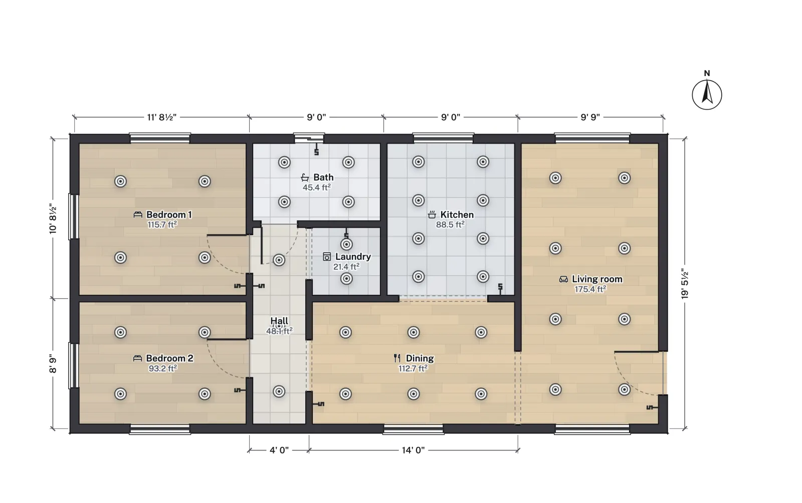
The plan below is the nearest FloorGen gets to an RCP: the 800 ft² two-bed ADU with Auto-place lights here run in every room, then the furniture, cabinets and fixtures deleted in a copy so only walls, openings, lights and switches remain. The door swings are still drawn, which a drafted RCP would usually leave out.
| Room | Net area | Cans | Estimate / target |
|---|---|---|---|
| Living room | 175.4 ft² | 8 | 191 / 150 lx |
| Bedroom 1 | 115.7 ft² | 4 | 136 / 100 lx |
| Dining | 112.7 ft² | 6 | 206 / 150 lx |
| Bedroom 2 | 93.2 ft² | 4 | 161 / 100 lx |
| Kitchen | 88.5 ft² | 8 | 335 / 300 lx |
| Hall | 48.1 ft² | 3 | 192 / 150 lx |
| Bath | 45.4 ft² | 4 | 261 / 200 lx |
| Laundry | 21.4 ft² | 2 | 214 / 200 lx |
That is 39 cans and 8 switches. Read it as a first pass, the way you would read any rule: eight cans in an 88.5 ft² kitchen is a lot of holes in a small ceiling, and fewer, brighter fixtures plus under-cabinet light would do the same job. In a real house the joists, ducts and an attic hatch would move several of them too.
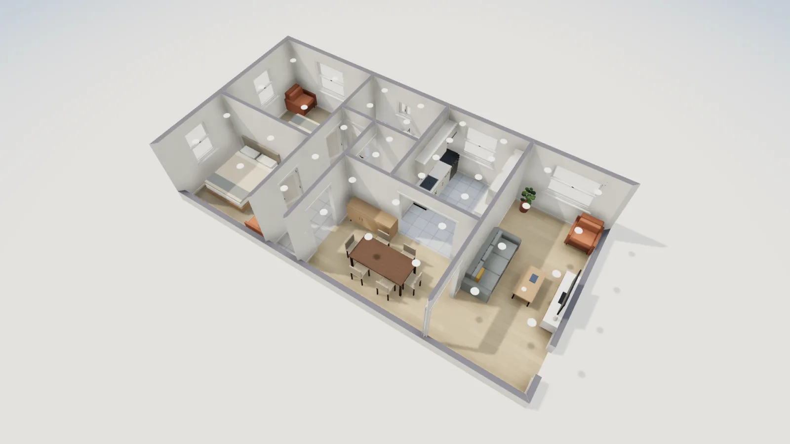
If you need a true RCP with heights, soffits and HVAC, draw it in a CAD tool. FloorGen can export the plan as DXF to start from (Export › CAD and 3D › DXF; see floor plan to DXF).
More from the blog
Guides7 min read
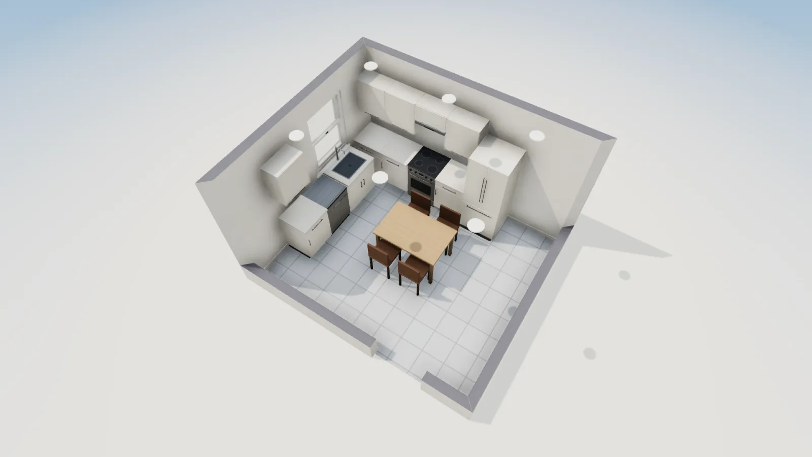
Recessed Lighting Spacing: How Far Apart and From the Wall
Guides6 min read
Ceiling Fan Size by Room: Blade Span Chart and Clearances
Guides5 min read
Nursery Room Size and Crib Clearances (With a Plan)