Guides9 min readVinit Kumar
How to Draw an Electrical Plan for a House (With Symbols)
How to draw a house electrical plan: the symbols for outlets, switches and lights, the order to place them, switch legs and circuits, on a real primary suite.
To draw an electrical plan, start from an accurate floor plan, then place the receptacles (outlets) along the walls, the lights on the ceiling and the switches beside the doors, using a standard symbol for each. Draw a curved dashed line, the switch leg, from each switch to the lights it controls, group the devices into circuits, and finish with a legend and a schedule. The plan shows where things go and what controls what; the wire routes are left to the electrician.
Below are the symbols most US house plans use, the order to draw them in, and a worked plan of FloorGen's primary suite. For outlet spacing rules in detail see outlet spacing for living rooms and bedrooms and kitchen outlet spacing; for protection by room, GFCI and AFCI requirements.
Electrical plan symbols
There is no single mandatory symbol set for house plans; most offices use variations of the same conventions, and every sheet should carry its own legend. These are the ones you will meet most often:
| Device | Symbol | Notes |
|---|---|---|
| Duplex receptacle | Circle with two short parallel lines through it, on the wall | The everyday 120 V outlet |
| GFCI receptacle | Duplex symbol marked GFCI or GFI | Bathrooms, kitchens, laundry, garage, outdoors |
| Weatherproof receptacle | Duplex symbol marked WP | Outdoors, usually GFCI too |
| Quad (fourplex) receptacle | Often a circle with four lines, or two duplex symbols side by side | Behind a TV or desk |
| Switched receptacle (half-hot) | Often a duplex symbol with half filled in; some legends mark it S | One half worked by a wall switch, for a lamp |
| 240 V receptacle | Varies: a circle with three lines, or a triangle or special-purpose symbol, labelled 240 V | Range, dryer, EV charger |
| Floor receptacle | Duplex symbol inside a square | In the floor, away from walls |
| Single-pole switch | S | Controls lights from one place |
| Three-way, four-way switch | S3, S4 | Lights worked from two places use two S3; add S4 for more |
| Dimmer | S with a subscript D, or marked DIM | Some legends use SD for a smoke detector, so check the legend |
| Ceiling light | Circle, often with four short rays | Surface or pendant fixture |
| Recessed light (can) | Small circle; some legends draw it in a square or with an X | See recessed lighting spacing |
| Wall light (sconce) | Circle or half circle on a short stem from the wall | |
| Ceiling fan | Circle with fan blades | Often with a light kit |
| Exhaust fan | Varies: often a square or circle marked F, or with blades inside | Bathrooms and laundry |
| Smoke / CO alarm | Often a circle marked SD (some legends SA) and CO | See smoke detector placement |
| Panel | Rectangle, filled or hatched | Label it with its amperage |
| Switch leg | Curved line, usually dashed, from switch to light | Shows control, not the wire's path |
How to draw an electrical plan, step by step
- Start from an accurate floor plan. Walls, doors with their swings, windows and the fixed items (cabinets, tub, appliances) all decide where devices can go. A copy of the floor plan with the furniture dimmed or removed works best. If you don't have one, see how to draw a floor plan.
- Place the receptacles. In bedrooms, living rooms and similar rooms, 2023 NEC 210.52(A) wants no point along the floor line of any wall space (2 ft or wider) more than 6 ft from a receptacle, which lets receptacles sit up to 12 ft apart. Kitchen counters have tighter rules (210.52(C)), and a bathroom needs at least one receptacle within 3 ft of the outside edge of each basin (210.52(D)). Mark GFCI ones.
- Place the lights. Decide the fixture for each room (a central ceiling light, a grid of cans, sconces), then place them. The 2023 NEC (210.70(A)) requires at least one lighting outlet worked by a wall control in every habitable room, kitchen and bathroom, and in hallways, stairways and attached garages, among others. Outside kitchens and bathrooms, a switched receptacle can generally stand in for it in a room.
- Place the switches. Put each one inside the room, beside the door on the latch side, so it is not behind the open door, and never inside a tub or shower space (NEC 404.4(C)). Use S3 switches at both ends of a hallway, a stair or a room with two doors.
- Draw the switch legs. A curved dashed line from each switch to each light (or switched receptacle) it controls. Keep the curves clear of each other so the control is readable.
- Add the fixed loads. Dedicated circuits for the range, dishwasher, disposal, washer, dryer, water heater, furnace or air handler, and any EV charger, labelled at the device.
- Group into circuits and add the panel. Tag each device with its circuit number and list the circuits in a panel schedule with breaker size and load. On many permit sets this is the electrician's job; on others it is part of the drawing.
- Finish the sheet. Legend, general notes (mounting heights such as "receptacles 12" AFF unless noted"), the panel location and the scale. Floor plan abbreviations explains AFF, TYP and the other shorthand.
A worked electrical plan: the primary suite
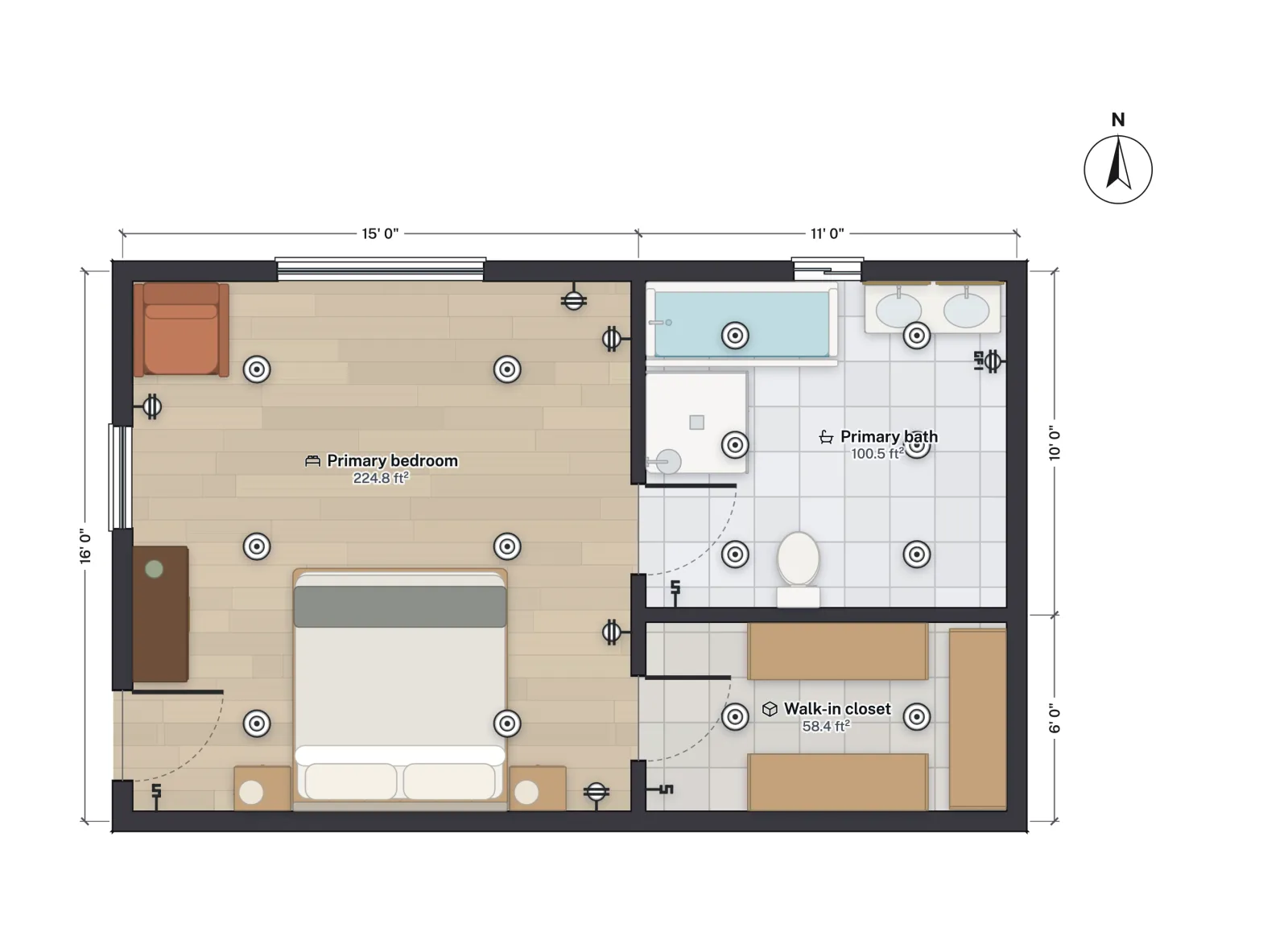
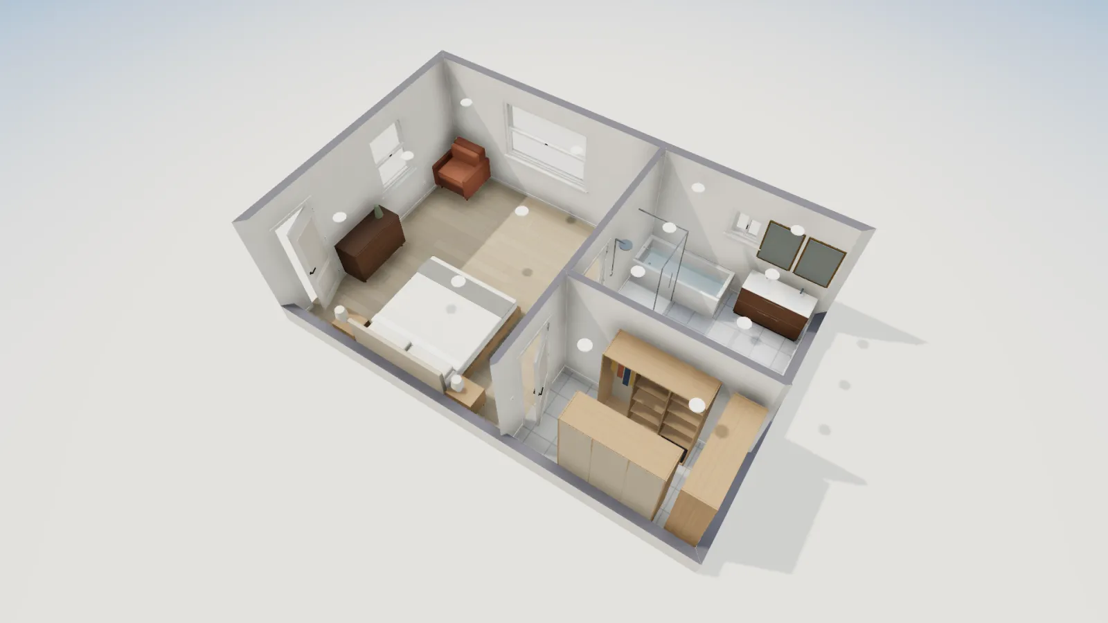
FloorGen's primary suite template has a 224.8 ft² bedroom, a 100.5 ft² bath and a 58.4 ft² walk-in closet (net, to the inner wall faces). The plan below adds six duplex receptacles around the bedroom about 12 in above the floor, a GFCI receptacle by the vanity, two switches we placed by hand, and the lights (and the closet switch) that FloorGen's Auto-place lights here chose for each room.
| Room | Lights added | Estimate | Target |
|---|---|---|---|
| Primary bedroom | 6 recessed cans, 900 lm each, linked to our switch | 126 lx | 100 lx |
| Primary bath | 6 recessed cans, linked to our switch | 235 lx | 200 lx |
| Walk-in closet (typed as storage) | 2 recessed cans and a switch | 117 lx | 75 lx |
Read the plan as a checklist. Every bedroom wall has at least one receptacle, with one at each side of the bed for lamps and chargers (the left one sits under the nightstand in the drawing); whether a layout passes 210.52(A) is still checked wall space by wall space against the code you build under. The bath's GFCI sits on the east wall beside the double vanity. Each room has one switch with its lights linked to it.
Why two switches were placed by hand: both doors sit close to a corner. Auto-place tries the latch side of the door first; when that stretch of wall is too short for a switch, it falls back to the hinge side, where the open door hides it. Left to itself, it would have put the bedroom switch behind the door and the bath switch on the wall inside the shower, where the NEC does not allow one. So the bedroom switch went on the south wall just past the corner, the bath switch on the bath's south wall just inside the door, and auto-place linked the new lights to them, as it does when a room already has a free single-pole switch. Auto-placed lights and switches are a starting point to check, not a finished design.
Drawing it in FloorGen
Receptacles, switches, dimmers, lights, fans, panels and boxes are library items. On the 2D plan they draw as electrical symbols: a receptacle as a circle with two lines on a short stem to the wall, a GFCI one marked GFI, a switch as an S, a recessed can as a ringed dot. Placing them works on every plan, the free one included.
The Electrical plan layer (View options, or ⇧E) adds the rest. Whether your plan includes the Electrical, Lighting and Daylight layers is listed on the pricing page; a layer your plan lacks shows a PRO pill. With the layer on:
- Switch legs. Select a switch, click Link lights, click each light it works and press Enter. An arc then runs from the switch to each light. A link accepts one single-pole switch, two 3-way switches, or two 3-way switches with up to four 4-way switches between them.
- Circuits. In the Electrical panel's Circuits tab, New circuit takes a name, breaker, voltage, GFCI or AFCI protection and a colour; Assign selection puts the selected devices on it. Each circuit shows its load in VA against its breaker, amber above 80% and red over it. The loads are placeholders to plan with: 180 VA per receptacle and a light's lumens at 80 lumens per watt, unless you type your own.
- Outlet hints. In projects on the IRC code profile, the Review panel's outlet check finds wall stretches too far from a receptacle, and Outlet hints draws its findings on the plan.
- Lighting. The Lighting layer colours the floor by light level and gives each room a badge such as "126 lx · target 100"; Auto-place lights here adds enough recessed cans for the room to meet its target, linked to a switch the room has or a new one by the door. It is a fixed rule, not AI, and costs no credits.
- The sheet. Export → Print set adds an Electrical sheet (E1.0) per floor that has devices, with the symbols, switch arcs, circuit tags, a legend, the circuit and fixture schedules, and an Electrical schedule page for the panel. The Schedule tab also downloads them as CSV.
All of it is advisory: FloorGen estimates loads and light levels to plan with, and does not size wire, calculate a service load or say a plan meets the NEC. Treat the E1.0 sheet as a clear set of intentions to discuss with your electrician; FloorGen's help centre has a guide to every option under Electrical, lighting and daylight.
Electrical plan checklist
- Every symbol on the sheet is in the legend.
- Receptacles meet the spacing rule on every wall space, with GFCI where your code requires it.
- Every habitable room, kitchen, bath, hall, stair and attached garage has a wall-switched light (or, outside kitchens and baths, an allowed switched receptacle).
- Every switch is on the latch side of its door and outside tub and shower spaces; halls, stairs and rooms with two doors have 3-way switches.
- Every light is on a switch leg, and every switch leg ends at a light or switched receptacle.
- Smoke and CO alarms are shown where the IRC and your state require them.
- Fixed appliances have their own labelled circuits, and the panel location is shown.
Related: Electrical plan maker · Plan checks against the building code
More from the blog
Guides7 min read
What Is a Reflected Ceiling Plan? How to Draw One
Guides7 min read
Recessed Lighting Spacing: How Far Apart and From the Wall
Guides7 min read
Floor Plan Symbols: Doors, Windows, Stairs and Fixtures