Electrical, lighting and daylight
Updated 9 min readNeeds a free account
Three plan layers show the wiring, the light level and the daylight of your plan: Electrical draws circuits and switch-to-light wiring arcs, Lighting a heatmap of light from your lamps, and Daylight the sun and sky through your windows. Whether they are in your plan is set per plan (see Plans and limits); placing outlets, switches and lamps works on every plan.
If the layers show PRO
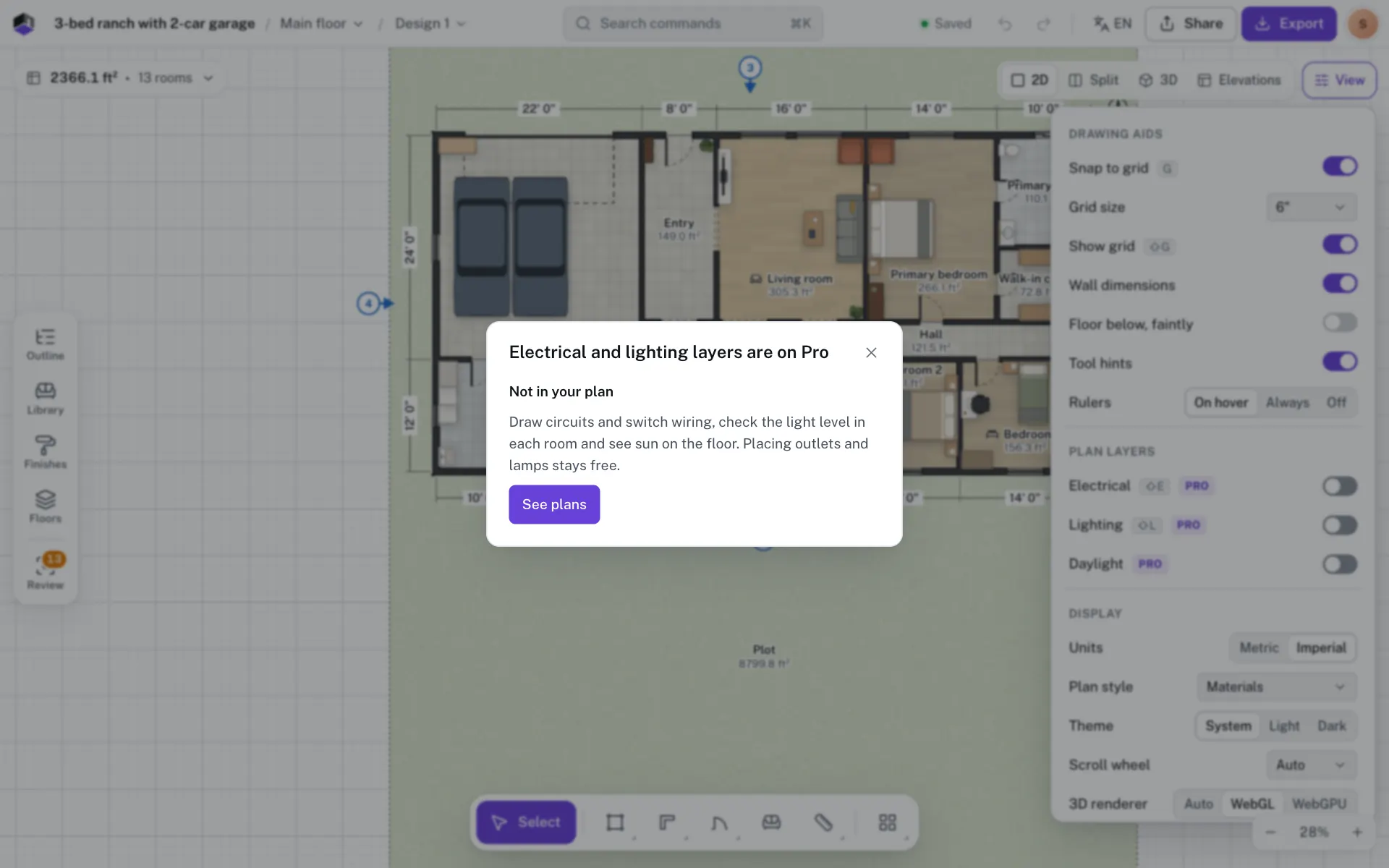
- Step 1: Click a layer
Click View at the top right and flip the switch of Electrical, Lighting or Daylight. A layer your plan lacks shows PRO.
- Step 2: Read the card
The card says the layers are not in your plan. A guest is asked to sign in first.
- Step 3: See plans or sign in
Click See plans to compare plans, or sign in if the card asks you to. A project that already has circuits opens and saves as before, with its devices drawn as plain symbols.
If View has no Electrical, Lighting or Daylight switch at all, the layers are not on for your account yet.
Turn on a layer
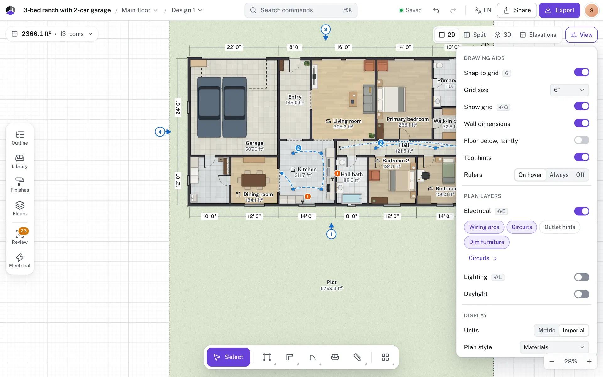
- Step 4: Open View options
Click View at the top right of the editor. The Plan layers section lists Electrical, Lighting and Daylight.
- Step 5: Switch a layer on
Flip its switch, or press ⇧E for Electrical and ⇧L for Lighting. The layers only change what the plan shows, never the plan itself, and stay on in this browser until you turn them off.
- Step 6: Pick what Electrical draws
With Electrical on, its chips choose Wiring arcs, Circuits (tags and outlets on no circuit), Outlet hints and Dim furniture. Circuits under them opens the Electrical panel.
While a layer is on, the left rail has an Electrical button. The panel has three tabs: Circuits, Lighting (each room’s light level against its target) and Schedule (the circuit and fixture schedules, with Download CSV).
Make circuits
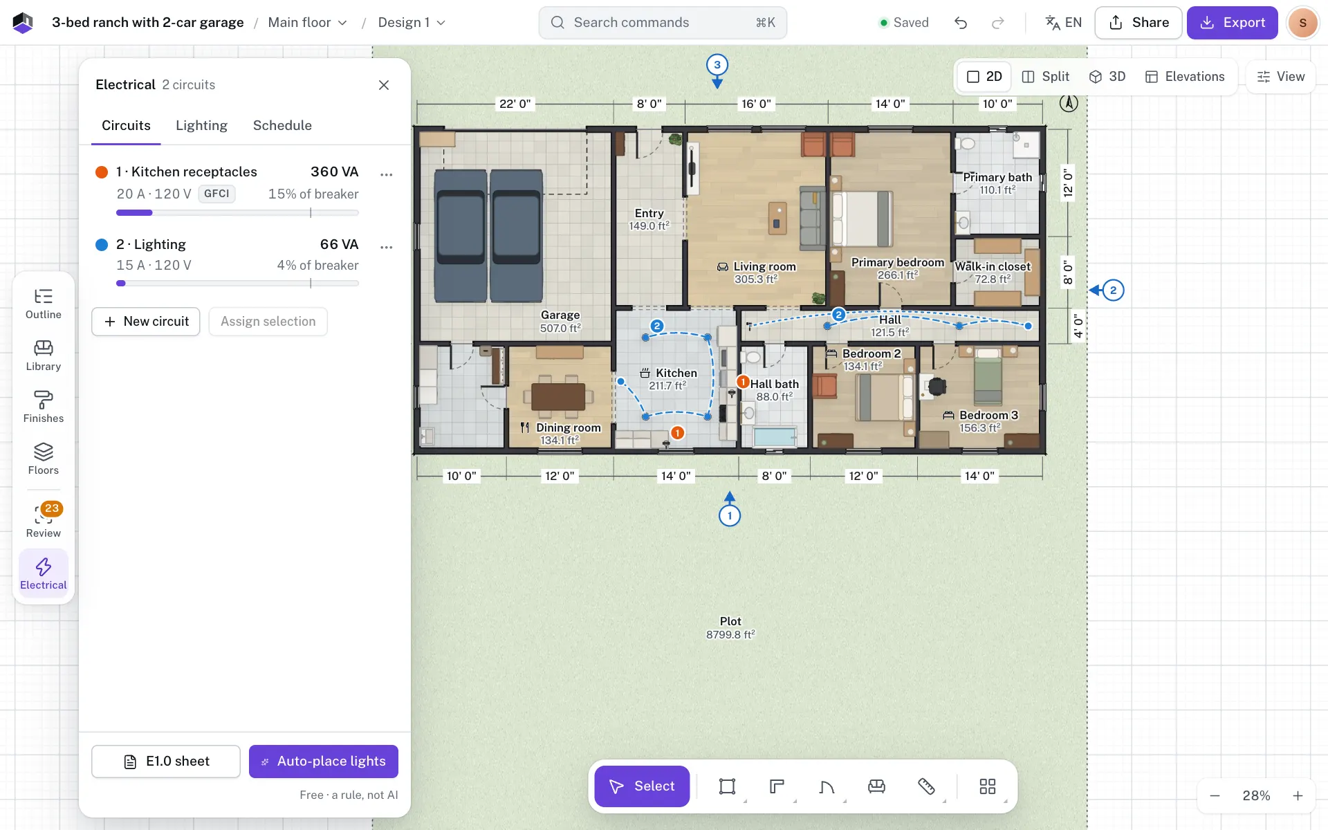
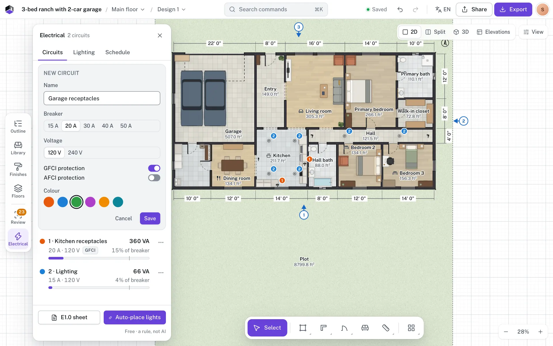
- Step 7: Add a circuit
In the Circuits tab click New circuit. Type a Name, pick the Breaker and Voltage, turn on GFCI protection or AFCI protection if it has them, pick a Colour and click Save.
- Step 8: Put devices on it
Select outlets, switches or lights on the plan, then click Assign selection and pick the circuit. With the Electrical layer on, the selection’s Circuit menu does the same.
- Step 9: Read the load
Each circuit shows its load in VA against its breaker. The bar turns amber above 80% of the breaker and red over it. A line counts the outlets and lights on no circuit; Select picks them.
A receptacle counts 180 VA and a light its lumens at 80 lumens per watt. To use your own figure, set the load on the device. A light’s Lumens are in its Light section; recessed cans and wafer lights have one too.
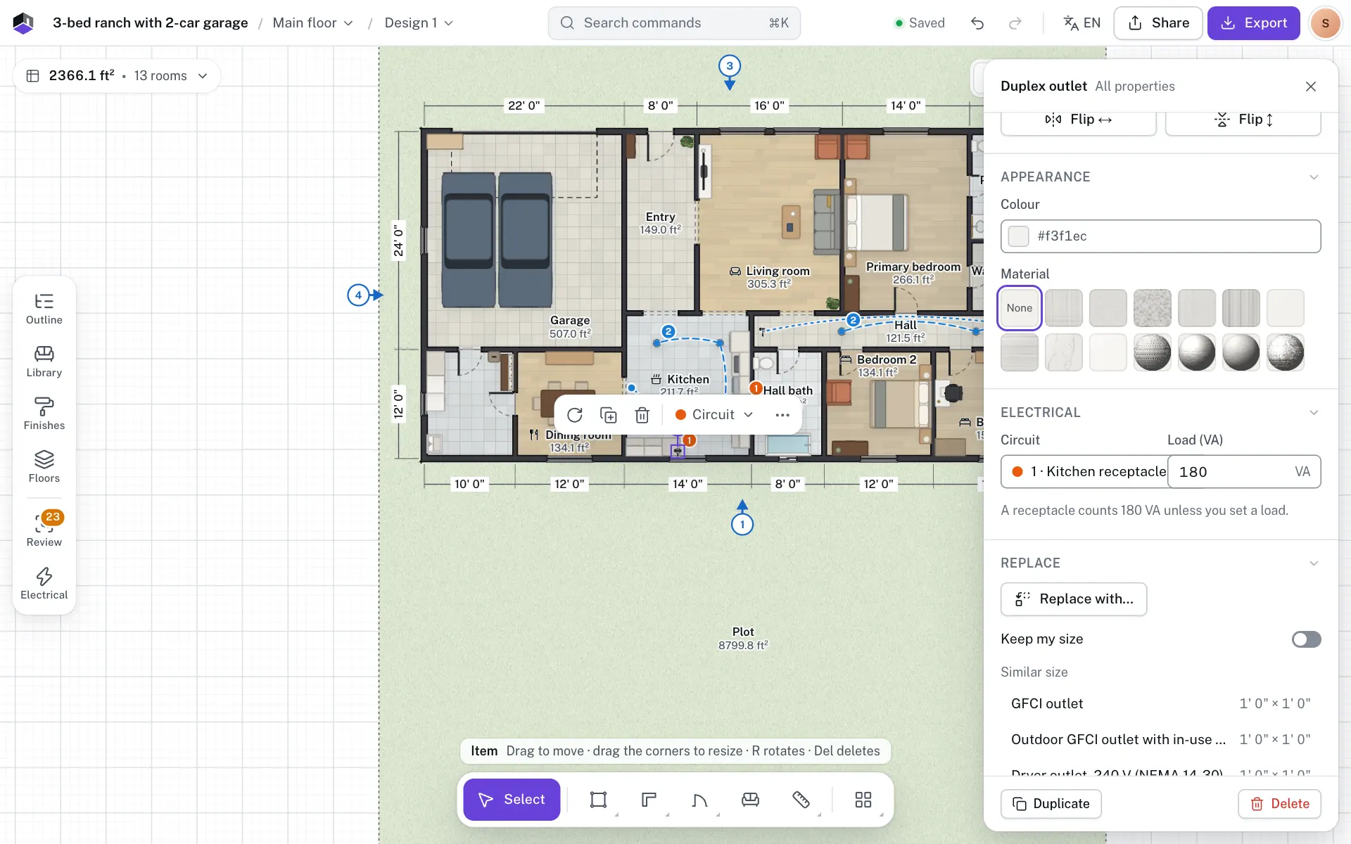
- Step 10: Select the device
Select an outlet or a light on the plan, click All properties and find its Electrical section. Circuit shows which circuit it is on.
- Step 11: Set its load
Type your own figure in Load (VA). The circuit’s load bar follows it.
Link a switch to its lights
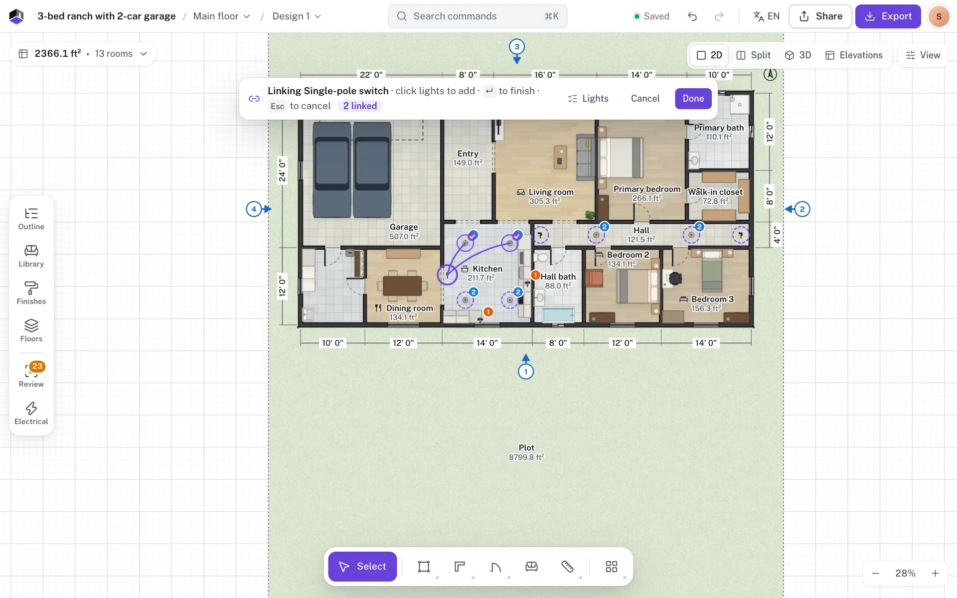
- Step 12: Select the switch
With the Electrical layer on, select a wall switch and click Link lights above it. A bar at the top says which switch you are linking.
- Step 13: Click the lights
Dashed rings mark what the switch can work: click each light, or tap it on a phone, and click it again to take it out. For lights worked from two places, also click a second 3-way switch. Without a mouse, open Lights in the bar and tick each light or switch.
- Step 14: Save the link
Press Enter or click Done. The link is one undo step, and an arc now runs from the switch to each light. Esc or Cancel leaves it unchanged; Unlink removes it later.
| Switches | Works the lights from |
|---|---|
| One single-pole switch | One place |
| Two 3-way switches | Two places |
| Two 3-way switches with up to four 4-way switches between them | Three to six places |
Any other mix is refused with a message that says what to change, and the bar stays open. One link works up to 60 lights. Deleting a switch or light takes it out of its link.
Check the light in each room
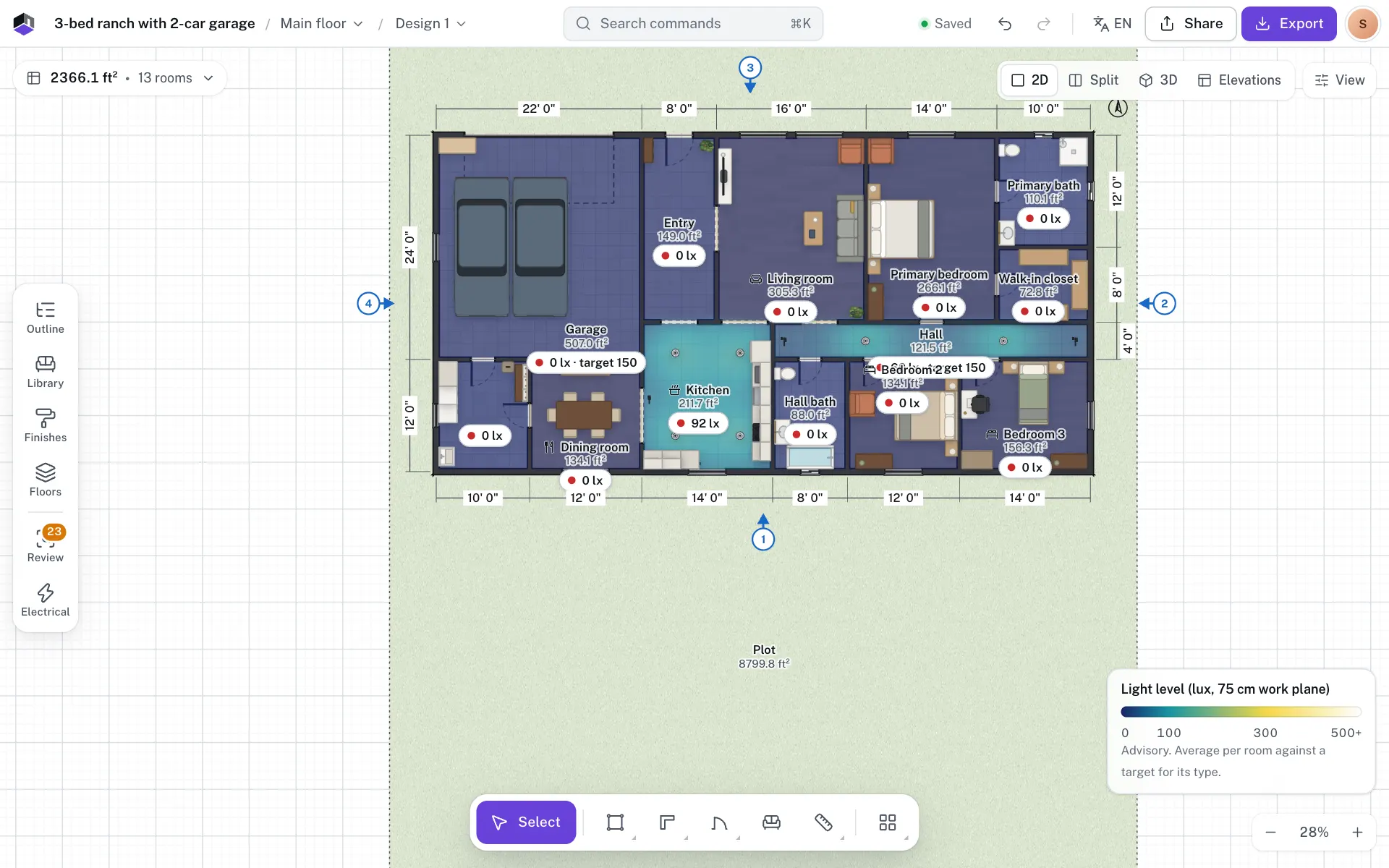
- Step 15: Turn on Lighting
Switch on Lighting in View options, press ⇧L, or right-click a room and choose Show light level. The floor is coloured by light level on a desk-high work plane.
- Step 16: Read a room’s badge
Each room has a badge, such as 126 lx · target 150. Light from a lamp stays in its room, or in an open-plan space, and walls stop it.
- Step 17: Read the legend
The legend at the bottom right shows the scale of the colours.
| Room type | Target |
|---|---|
| Kitchen, study | 300 lx |
| Bathroom, utility | 200 lx |
| Living, dining, kids room, toilet and rooms with no type | 150 lx |
| Bedroom, hall, mudroom, closet, garage | 100 lx |
| Store | 75 lx |
| Sauna, cellar, balcony, porch | 50 lx |
A room meets its target at or above it, is below target at half or more, and too dark under half. The targets are rules of thumb for homes, not a standard.
Add lights automatically
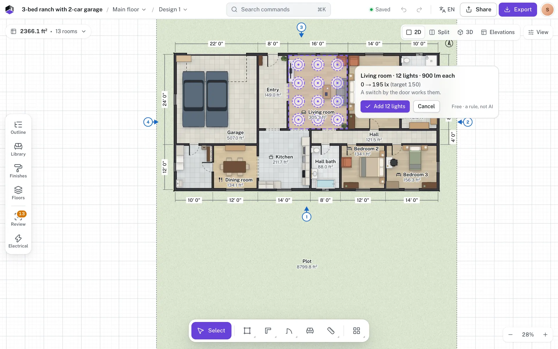
- Step 18: Open Auto-place
Right-click a room and choose Auto-place lights here, or click Auto-place lights in the Circuits tab for the selected room, or the first room below its target.
- Step 19: Check the ghost lights
Ghost lights show where recessed cans would go, sized so the room meets its target, and a switch that works them: one the room has, or a new one by the door. The card beside the room shows the light level before and after.
- Step 20: Add or cancel
Click Add 4 lights (the count varies) to add them as one undo step, or Cancel (Esc). Lights already in the room count and stay where they are.
Auto-place is Free · a rule, not AI: the same room always gets the same layout, and it costs no credits.
See daylight
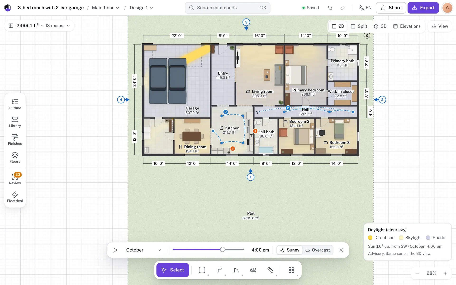
- Step 21: Turn on Daylight
Switch on Daylight in View options. A time bar sits above the tool dock.
- Step 22: Set the month and hour
Pick the Month and the Hour of day from 6 am to 8 pm, or click Play the day. They are the same month and hour as the sun in the 3D view, so changing one changes the other.
- Step 23: Switch the sky
Sunny shows patches of direct sun and sky light through the windows. Overcast shows the daylight factor, the share of an overcast sky’s light that reaches the floor, with a badge per room. Close daylight turns the layer off.
Eaves, trees and neighbouring buildings are not modelled.
Print and export
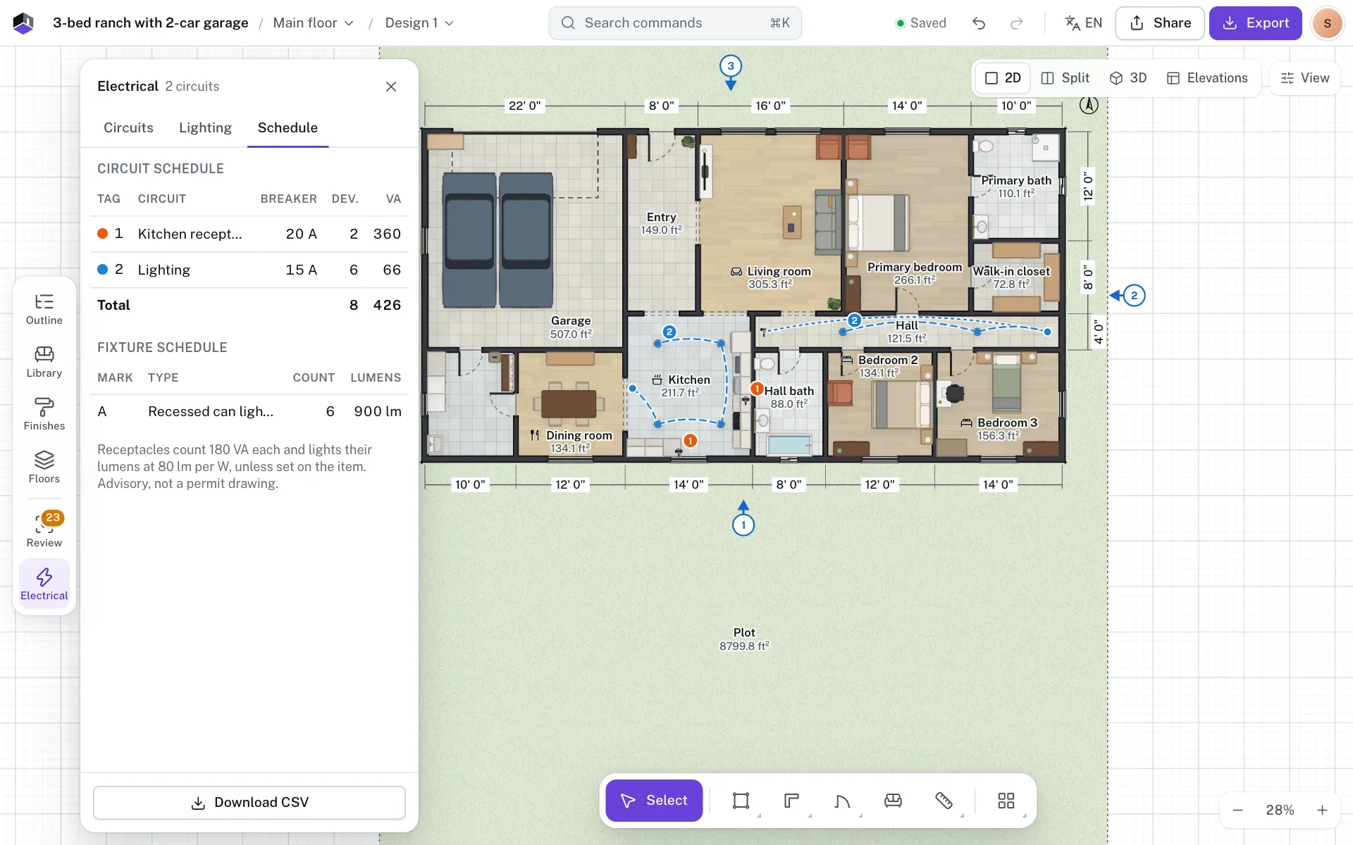
- Step 24: Open the Schedule tab
In the Electrical panel open the Schedule tab and click Download CSV.
- Step 25: Add it to the print set
In Export, open Print set. Electrical sheet (E1.0), a page per floor with devices, arcs, circuit tags, a legend and the schedules, and the Electrical schedule are on; turn one off to leave it out. See Export a print set.
- Schedules and budget has an Electrical section with each circuit’s load and the fixtures, and CSV downloads it. See Schedules and budget.
- Agents can read and change circuits, links and light levels through FloorGen’s MCP tools. See MCP tools and toolsets.
Questions
Why do the layers show PRO?
Your plan does not include them. See If the layers show PRO.
Where are the outlet-spacing hints from?
From the Review panel’s outlet check, which runs in projects on the IRC code profile. See The Review panel. Outlet hints draws its findings on the plan.
Are circuits shared between designs?
No. Each design of a floor keeps its own circuits and links, so you can compare two layouts.
Why is a room dark with lamps in it?
Only lamps in the same room, or the same open-plan space, light it. Check each lamp’s Lumens, or use Auto-place lights here.